Take control of slide timing yourself.
Use the butttons below to step though.

Each yellow triangle represents a microprocessor controlled switch
that can connect to any of three nearby electrodes (circles X, Y and Z).
that can connect to any of three nearby electrodes (circles X, Y and Z).
3D E-SCAN survey setup involves installing electrodes at every station on the survey grid.
While a conventional survey would eventually install electrodes at all of these stations as it progresses, 3D E-SCAN wires all of these stations at the outset. Then, instead of having just a few in-line electrodes to measure with, each E-SCAN "shot" can be measured at 40 to 100 different grid electodes, located in all directions from the input current electrode.
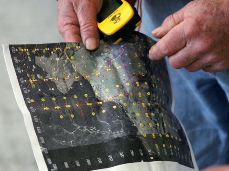
A computer-generated system layout is printed over an aerial photograph of the survey area, as a guide for the field crew in laying out the wire and electrode network.
No pre-installed grid is needed. Each station on the map has been pre-programmed into the crew's GPS units, leaving the choice of access route up to the crew person who must negotiate fences and obstacles while laying wire in the most secure location possible.

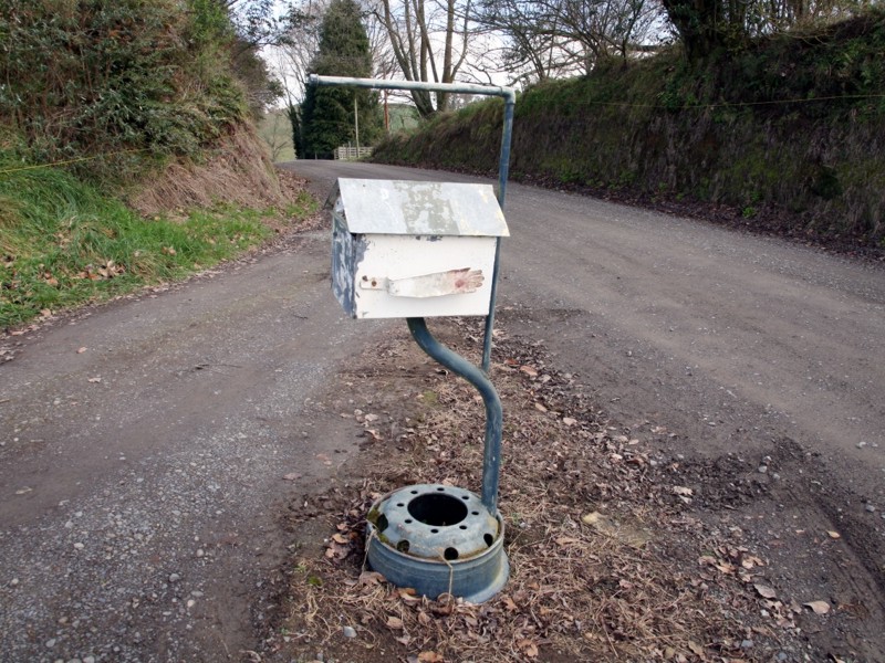
One of 127 system "boxes". The outer pairs of terminals are connected into the two-conductor main line (red).
The centre three terminals connect to three electrode stations. Everything is water-proof and almost indestructible.
Connections can be made with "mitts on" at -40 degrees. Mil spec electronics can take direct tropical sum.
The centre three terminals connect to three electrode stations. Everything is water-proof and almost indestructible.
Connections can be made with "mitts on" at -40 degrees. Mil spec electronics can take direct tropical sum.
These microprocessor switchboxes are daisy-chained in long lines using inexpensive blasting wire. This offers the greatest flexibility of layout, and avoids the cost, risk and, in rough terrain, the inflexibility of expensive multi-conductor seismic cables or other specialized wiring.
A two-foot (60 cm) steel electrode is all that is needed here, serving initially as a measurement electrode, and eventually as a curent injection electrode.
The wiring setup is very fast... actual measurement "shooting" usually starts late on the third day of setup. Cleanup is usually 2 days, following the last measurement shot.
Time and crew requirements for E-SCAN are similar to that needed to operate a conventional dipole-dipole array survey over a similar area. The results are anything but similar... 50 times the number of raw measurement data, acquired as a true 3D uniformly-distributed, multi-directional field data set. <
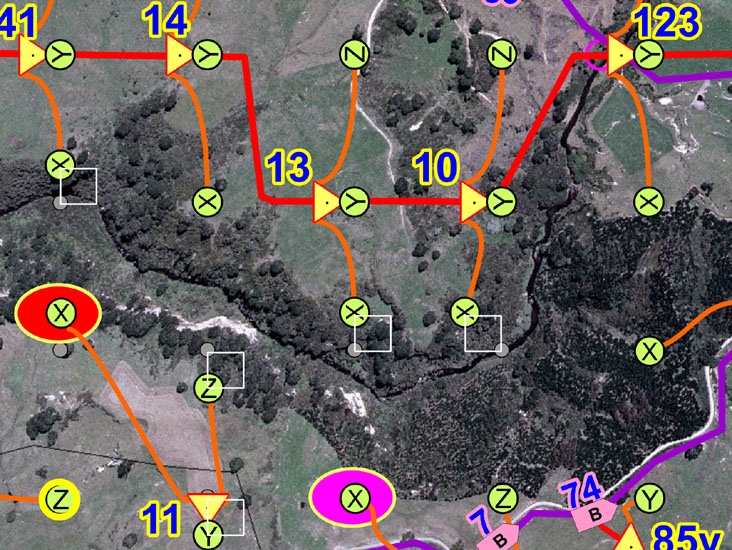
Yellow triangles are the switch "boxes". X, Y and Z are nearby electrodes connected to a box. Red is a box line, one of up to 20 branches
off the (purple) main line leading back to the controller site. The coloured ovals mark two X electrode locations showing new wire breaks,
detected in a 10 minute total-system scan run every morning and through the day. Problems are detected and fixed quickly and precisely.
off the (purple) main line leading back to the controller site. The coloured ovals mark two X electrode locations showing new wire breaks,
detected in a 10 minute total-system scan run every morning and through the day. Problems are detected and fixed quickly and precisely.
This layout adjusts for a river with dangerously steep areas. Grey dots show the planned electrode sites, while X, Y and Z show actual setups. Crew go to alternate locations when a site appears to be unuseable (too dangerous, or maybe located smack in the middle of a feedlot filled with cattle).
Boxes 123, 10, 13 etc. are on a branch line serving the north side of the river. Branch boxes #74 and # 7 connect other lines.
In operation, a digital call to box 13 may request that a connection to electrode 13-Z. The box complies, self-tests, then reports its action back to the main controller: "Connected to 13-Z, ready for measurement." Ten seconds later, measurement complete, control may digitally ask for 13-X to be connected next.
With current being injected at one electrode, a fully digitized and stored measurement sequence at one of the several hundred other electrodes is completed every 9-10 seconds, in average signal conditions. That's 6 confirmed and post-shot tested measurements per minute, or 360 per hour. Time between current connections at successive input stations is less than 1 minute under typical conditions, so hour-to-hour shooting is over 95% straight data logging.
In a single day, 3D E-SCAN logs more data than would be collected in the entire equivalent conventional resistivity survey, over the entire property.
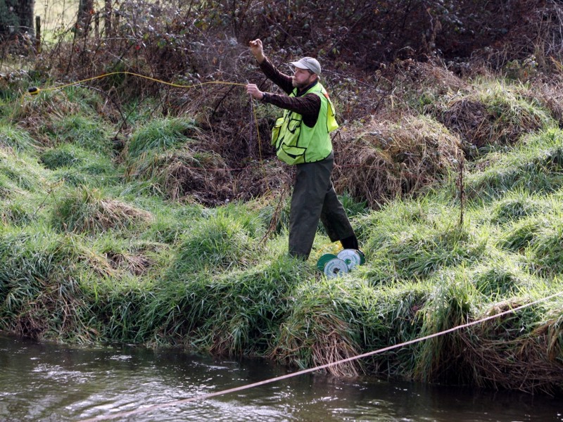
Suren "Ernie" Holbek, from Mt Shasta, California, get some
NZ morning air as the E-SCAN grid shapes up to be ready for shooting.
NZ morning air as the E-SCAN grid shapes up to be ready for shooting.
Near box 123, a rock in mid-flight takes the current feeder wire across the river to the area served by boxes 123, 10, 13 (previous image). The red duplex wire is already across. Crew on the other side will connect through, completing one of the 15 wired sub-areas on this grid.
Most of the wire in an E-SCAN layout is signal-level only, i.e. less than one volt.
Only the wire feeding the injection current electrode needs to be managed for public (and animal) safety.
Only the wire feeding the injection current electrode needs to be managed for public (and animal) safety.
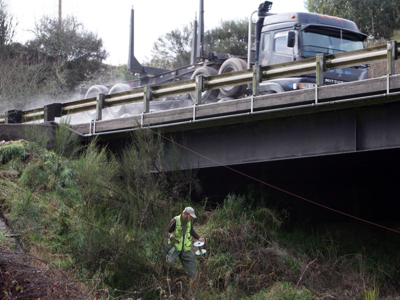
Bridges are helpful for establishing river crossings. Where traffic is heavy, wire crossing on the road is not advisable and usually not allowed.
A bridge makes a handy underpass for accessing the other side... lines can fan out and cover a large area from a single crossing.
With high trees lining roads, wires can safely cross roads, lanes, cattle-tracks and driveways high in the air.
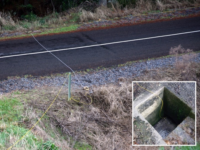
On little-used roads, heavily insulated wire brought especially for the purpose can be laid across and staked off at each side.
Sometimes, a corrugated steel or plastic culvert is available. Even this concrete drain was put into service to get a key wire across a road where no trees or other options existed, and traffic was a problem.
The trick is to use these aids quickly and decisively, so that the flow of wire layout is not delayed. Experienced crews understand this and usually pride themselves not just on innovative ways to get the job done, but fast innovative ways.
In New Zealand it was, I'm told, inevitable that we would use a "potato gun" somewhere to get a wire across a some impossibly difficult spots. It worked. 2.5 inch diameter plastic pipe, screw-on plastic end cap, barbecue piezo-igniter, hair spray, potato... use your imagination.