3D E-SCAN technology improves on each of the three main limitations that prevent conventional DC resistivity surveys
from mapping deeper into the earth:
1. Loss of signal strength occurs at deeper levels,
2. The space required for surface array layout becomes unmanageable for greater depths,
3. Reduced resolution (due to sparse deeper data) limits deep target recognition.
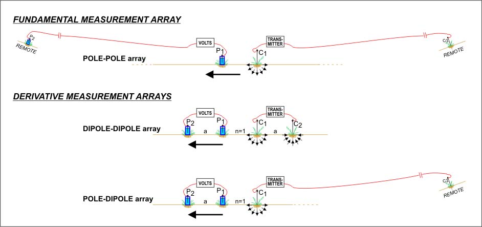
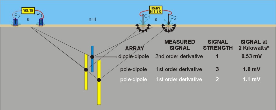
This page compares the currently best-performing (pole-dipole array) and the historically most-used (dipole-dipole array) conventional DC resistivity surveys with the basic measurement array unit of 3D E-SCAN, the pole-pole array. These arrays are diagrammed in the top image at right. All employ four electrodes. Pole-dipole employs a stationary remote "infinite" electrode, leaving three electrodes to be positioned on the line for various measurements. Pole-pole employs a second remote electrode, leaving just two electrodes for each measurement.
The reference to derivatives will be further addressed below.
QUICK SUMMARY:
- Dipole-dipole is the easiest, fastest, and lowest cost survey method, but produces the least penetration, delivers the poorest signal strength,
takes up the most surface real estate per unit penetration, and suffers the greatest loss of data from sources of near-surface
distortion.
- Pole-pole is the most complicated, slowest, and most expensive survey method, but produces the greatest penetration,
delivers the highest signal strength, takes up the least surface real estate per unit penetration and suffers the least loss of data from s
sources of near-surface distortion.
- Pole-dipole array performance lies in the middle, in every category.
What's popular? In general, if a target can be reached by dipole-dipole array survey, that method is usually employed, being comparatively cheap and
fast as long as the transmitter current source can be backpacked along the lines.
For deeper targets, or where backpacking is not practical, a pole-dipole array survey delivers significant advantages in both effective penetration and signal strength.
Pole-dipole's requirement for a stationary transmitter means high-power equipment can be used, further boosting signal and depth performance.
Any survey requiring a transmitter of greater than 2000 watts power is usually undertaken as a pole-dipole survey, since the transmitter can not be moved along the lines. Outside of E-SCAN's automated application, the pole-pole array is almost never used in modern resource exploration.
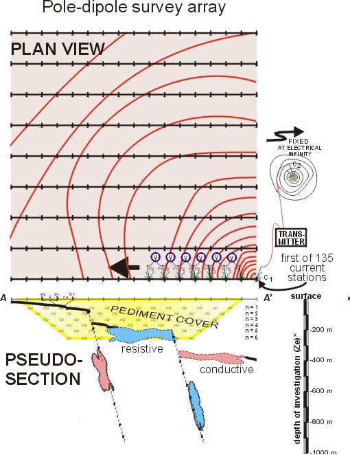
Image # 2 (from top) shows the four electrodes used for a single dipole-dipole survey array measurement. For discussion purposes, this example shows a setup with four dipole separations (n=4) distance between the current and potential dipoles, of a usual
range of separations of n=1 to n=7. The measurement shown here is plotted at the effective penetration ("Ze" of
Edwards, 1977) depth for that array geometry. Using an effective depth Ze, computed for each array and spacing, allows direct comparison between different array data on the same pseudosection plot. Remember, we are concerned about three factors for each plotted Ze depth: signal strength remaining high enough to allow measurements, array layout space requirements along surface remaining reasonably compact, and having the ability to resolve deep targets.
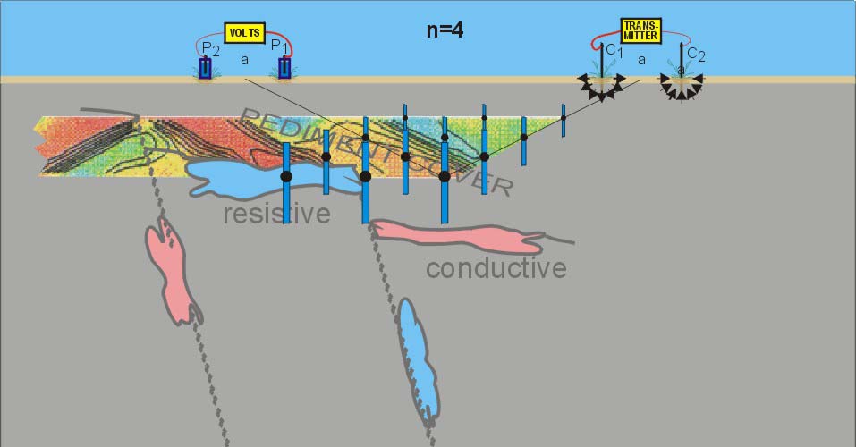
Image 3 shows a pole-dipole array measurement using
three of the four electrodes. The measurement's effective depth is greater, signal level is greater, and the total length of the surface setup is smaller. A good start.
In image 4 a second pole-dipole array measurement uses the other current electrode location to generate a completely different earth measurement. This measurement's effective depth is greater still, signal level is greater, and the total length of the surface setup is the same as the dipole-dipole setup. Instead of a single dipole-dipole measurement, we have two different samples of the same ground, with deeper information, and at higher signal levels. This is the essence of why explorers who need to go deeper, or who face signal difficulties due to local conditions, will opt for a pole-dipole array survey over the (usually) lower-cost dipole-dipole array option.
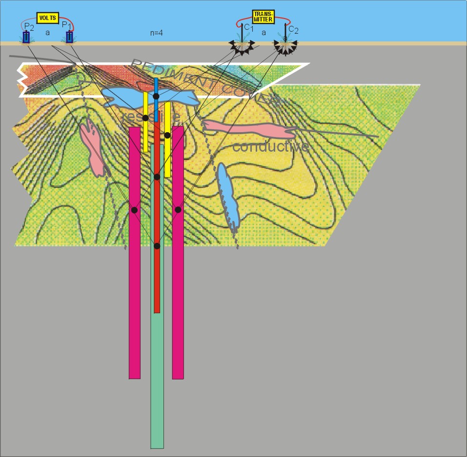
Image 5: Having established a second distant, permanent "infinite" electrode, this one for measurements, E-SCAN's pole-pole or "two-electrode" array can now make use of the four electrode sites in even more advantageous ways. Using the two centre electrodes, a pole-pole measurement that takes up only 2/3 of the surface layout distance of the original dipole-dipole array measurement delivers 2.5 times the effective penetration (Ze), at 15 times the signal strength! This is your first taste of just how much information is lost when the fundamental field measurements are subtracted from each other in the dipole survey arrays, and how much is re-gained when
cost-effective pole-pole measurement capability is enabled.
Image 6: Among the four electrodes, there are four unique combinations of current and potential electrodes.. here, another selected pair is spaced a little wider, providing deeper information, still at a very high signal level.
Image 7: Another pairing.
Image 8: All four pole-pole array measurements are now shown. Each pole-dipole measurement is a derivative of two of the pole-pole data. The second-order dipole-dipole measurement derives the two pole-dipole data, or from all four pole-pole data. By making the effort to establish two remote reference electrodes, thus enabling two-electrode (pole-pole) array measurements, the depth and information content of these four fundamental data is accessed from just four electrodes. You can calculate any of the derivative data from these four, but the reverse is not true - the deeper fundamental data can not be recovered separately from the derivative values. A dipole-dipole array survey's data are what they are, shallow, low-signal, minimum information content. The four pole-pole array data contain all of the information of all of the dipole-dipole and pole-dipole survey data obtained from the same electrodes. As a further bonus,- the pole-pole
fundamental data absolute voltages represent the primary, direct data values used as input (and output) used by 3D model inversion processing. Derivative data (as differences or gradients) are comparable in the inversion process only after interim inversion voltages are further computed as equivalent array derivatives, making the interactive feedback process less direct, blurred, and as a consequence less effective in forcing an objective, unique-as-possible earth model solution.
Here is a reminder of what 3D E-SCAN's automated version of pole-pole array measurements delivers to the interpretation process, as compared to the most effective present-day conventional survey array,- pole-dipole. Slide show:

You can click
here for a summary image showing where the 15-panel slide show takes you.
The use of reduced-information derivative values to constrain 3D inversion model development is a significant disadvantage, proportional to the number of derivatives involved in each datum... dipole-dipole data are second-order derivatives, remember?
It is useful to reinforce the fact that the fundamental pole-pole data are
individually more effective in guiding (forcing) the developing 3D earth model inversion. A compounding of this advantage occurs when the pole-pole array data set steps out from its conventional along-the-line survey arrangement and through E-SCAN technology measures cross-line, and diagonally, in fact everywhere, at every station on the property-wide grid setup. A few hundred one-directional data become thousands of all-directional, dense and uniformly sampled data, quite a different set of conditions to be matched by any 3D model inversion processing.
Conventional surveys deliver a single strip of gradients (voltage differences, as n=1 to 7 or n=1 to 10) always in one direction, radially outward from the centre of the potential field. For the same potential field, established by current injection at the same grid station, 3D E-SCAN technology allows measurement (not of gradients, but) absolute voltages at all of the grid stations surrounding the injection point, effectively mapping and defining the nature of the entire potential field as it surrounds the current injection point.
The information/data difference is immense. The multi-directional E-SCAN pole-pole data set would allow calculation of equivalent strips of dipole data that could be plotted radially outward in all directions from the current station,- the effective equivalent of having run four or eight separate, complete dipole surveys of the property, in varying survey line orientations. But with the advantage of not having derivative (dipole) data, but full-information, maximum-depth fundamental pole-pole data.
Effect on interpretation: The inversion process repeatedly (every iteration, for 20, 30, maybe 100 iterations) solves for a surface potential field (2D field of voltages) which it then compares to the observed field data, to see how close it is getting to reproducing a 3D resistivity model that could cause what we saw at surface in the field survey results. When the algorithm compares it's model-development progress to conventional pole-dipole or dipole-diplole field data (the sequence or strip of gradients or differences in a line out from the current site), it selects the few absolute voltage values that it needs to calculate derivatives (gradients, differences) that are equivalent in location to those we measured in the field. So with derivative data, one (or a few) sequence of gradients (not even absolute values) is the basis of comparison to see how the latest inversion model is doing in matching the field data. Because the field data are derivatives, the the matching can be done only after the computed model voltages field have been calculated (degraded) into equivalent derivatives (gradients, differences) for comparison. How inefficient,- and remember that the data we are trying to match are the dipole-dipole or the pole-pole measured values, when we could be comparing, matching and adjusting the model each iteration with the actual fundamental potential field voltages. Efficiency aside, which model will be most objective, most comprehensively constrained... one matching 256 short strips of one-direction voltage differences, or one matching 256 complete, area-wide absolute-voltage-mapped potential fields?
The example pictured here shows the best-alternative conventional data set (pole-dipole), and the 3D E-SCAN data set. Consider how the 3D inversion works. the 3D inversion development uses as its guide a measure of the degree of
Absolute voltages, all relative to a the
same single remote point of reference.
The term "derivative" is used loosely here to describe a real and precise effect. A "difference" field or a "difference" voltage (potential difference) would also suffice, perhaps more accurately. But this is not intended to be a working mathematical characterization,- just an easily repeatable reminder of the consequences of electrode positioning in a survey: the loss of signal strength and information by the subtraction or cancellation of primary or "fundamental" values... leaving a difference or, loosely, a derivative.
Summary: Avoiding using a measurement dipole avoids signal cancellation, thus allowing maximum-signal (maximum information) measurements. When the four-electrode measurement setup involves two dipoles, the current dipole delivers a subtracted net field - the first derivative - that is left over after a negative field is overlapped onto a positive field, from which a second dipole measures a voltage difference - effectively a derivative of a derivative, or, a second order derivative.
For our purposes: Derivatives mean reduced information,- subtracted remainders of fundamental information. Fewer is best. The dipole-dipole array uses two; the pole-dipole array uses one; the pole-pole array uses none.
Each pole-dipole measurement contains more information than the dipole-dipole array, covering a greater vertical sampling interval with higher signal resulting from a simpler stimulation patterns - a single current point potential field that is not decimated by a nearby opposite-polarity field. The dipole-dipole measurement is actually a derivative of these two pole-dipole measurements - one can calculate the dipole-dipole plotted value by subtracting the first pole-dipole measurement from the second, effectively subtracting what happens due to one current injection from what happens due to another.... which is precisely what is going on when the measurement is made in the dipole-dipole setup. Much of the deeper pole-dipole information, and a lot its signal strength, is subtracted away, leaving the smaller signal plotted at a shallower depth. This is another way of showing that there is more "information" in each of the pole-dipole measurements, representing what's going on across the deeper and wider sample interval (the 50% bar). When it comes to inversion modeling processing, far better to have two separate deeper-information data to work on, to accommodate in the developing model, than just the single dipole-dipole derivative value.
The dismal operating economics of conventional pole-pole surveys are completely overcome with 3D E-SCAN's high degree of automation of field processes. This enables E-SCAN to acquire a 15,000 datum field measurement set in 10 days, as compared to the four years (at 7 days per week) required to obtain the same data with conventional pole-pole array operations. Conventional pole-pole survey is not only difficult to set up initially, but it is also time consuming to to reposition the additional long wire needed for every measurement.
Up to 2000 watts of transmitter capability can be backpacked along survey lines to get the full benefit of the dipole-dipole array's operating efficiencies. This includes many battery powered units, and backpack motor-generator-powered transmitter systems (Phoenix Geophysics, formerly McPhar) up to 1.5, even 2 kilowatts. Once the required power levels exceed this level, stationary transmitters are used with pole-dipole arrays. Motor-generators powered systems (Walcer-Huntec, Scintrex, Zonge, others) providing up to 20 kilowatts (20,000 watts) of power may be employed. The >35 kilowatt systems (Anaconda, Asarco, Premier, various USSR entities), most originating from the porphyry copper boom days many decades ago, are today mostly irrelevant, strongly outperformed in every aspect by 3D E-SCAN.
Edwards*, L.S. 1977. A MODIFIED PSEUDOSECTION FOR RESISTIVITY AND IP: Geophysics 42, 1020 (August 1977)
*U.N. Development Program, Rangoon, Burma
ABSTRACT: Dipole-dipole induced-polarization measurements are commonly presented as pseudosections, but results using different dipole lengths cannot be combined into a single pseudosection. By considering the theoretical results for simple earth models, a unique set of relative depth coefficients is empirically derived, such that measurements with different array parameters will "mesh" smoothly into a combined pseudosection. Application of these coefficients to a number of theoretical and field cases shows that they give reasonable results when applied to more complicated models. The empirical coefficients are compared with Roy's theory of "depth of investigation characteristic," and support that theory, if a modified definition of "effective depth" is accepted. This leads to an absolute depth scale for the modified pseudosection. It is shown that rough estimates of the depth to the top of an anomalous body can be made directly on the pseudosection, at true vertical scale. This definition of effective depth is applied to other electrode arrays. It is shown, by examples, that the resulting pseudosections give consistent estimates of depth to top, within the characteristic anomaly patterns of each array. The effective depths for various arrays are compared; the results agree with the traditional applications of each array.
For all arrays, the nominal depth of investigation, or effective penetration, is proportional to the distance separating the current input electrode(s) from the measurement electrode(s). Wider spread = deeper sampling.
 Still employing the same span of electrodes along the line,
 there is yet more intelligence that can be acquired by more
effective use of electrode resources. With a second, stationary "infinite" electrode relocated far from the site, only two
electrodes, one current, one measurement, are active on the survey site, each referenced to its corresponding "infinite" site.
Above, the pole-pole array measurement using the sites of just the C1 and P1 electrodes is shown. More than twice the depth
of the dipole-dipole measurement, and 15 times the signal level! 50% deeper than the deepest pole dipole array measurement,
and with 7 times the signal strength. How is this possible?
First, the signal advantage gained for the pole-dipole array measurement (by establishing the distant current
"infinite" electrode) is maintained. No nearby opposing-polarity current field to cancel signal.
Second, instead of measuring just the difference in voltage between P1 and P2 (as both of the dipole arrays do),
pole-pole measures an absolute voltage, relative to the distant "infinite" reference. A big, robust, deep-sampling, high-information
signal, representing 100% of the signal that can theoretically be measured using DC resistivity/IP arrays of any configuration.
 A second pole-dipole measurement can be made,
 using the C2 location, and the relocated "infinite" current electrode.
At n=5, it is almost twice as deep as the n=4 dipole-dipole datum that employs the same span of electrode sites along the line.
Each pole-dipole measurement contains more information, covers a greater vertical sampling interval, with stronger signal
resulting from a simpler stimulation pattern - a single current point potential field that spreads uniformly in all directions.
The dipole-dipole measurement is actually a derivative of these two pole-dipole measurements -
one can actually calculate the
dipole-dipole plotted value by subtracting the first pole-dipole measurement from the second, effectively subtracting the signal
due to one current injection site from the signal from an adjacent site.... which is precisely what is going on when a measure-
ment is made in the dipole-dipole array setup.
For the dipole-dipole datum, much of the deeper information, and a lot of signal strength, has been subtracted away,
leaving the smaller signal plotted at a shallower effective depth of investigation.
When it comes to inversion modeling processing, it is advantageous to have two separate deeper-information data to work on,
helping to force more detail to be accommodated in the developing model, rather than using just the single dipole-dipole datum.
The other current electrode has been positioned at the remote "infinite" location where
it would remain for the duration of a pole-dipole survey.